Crazy Climber (Model Racing bootleg): Difference between revisions
From Citylan
Jump to navigationJump to search
mNo edit summary |
mNo edit summary |
||
| Line 2: | Line 2: | ||
|+ style="background:silver" | EMU Infos | |+ style="background:silver" | EMU Infos | ||
|- | |- | ||
|dumper || Any | |dumper || Any, f205v | ||
|- | |- | ||
|date || 10/05/2013 | |date || 10/05/2013 | ||
| Line 31: | Line 31: | ||
!position | !position | ||
!function | !function | ||
|- | |||
|1x || [[Z80|Z80CPUB1]] || || piggyback 6d || 8-bit Microprocessor - main | |||
|- | |||
|1x || [[AY-3-8910|AY-3-8910]] || || 6r main PCB || Programmable Sound Generator - sound | |||
|- | |||
|1x || [[LM2900|MC3301P]] || || 8p main PCB || Quad Operational Amplifier - sound | |||
|- | |||
|1x || oscillator || 18MHz || 0a ROMs PCB || | |||
|} | |} | ||
| Line 40: | Line 48: | ||
!position | !position | ||
!status | !status | ||
|- | |||
|6x || [[2716|TMS2716]] || 6a,6c,6h,6k,6l,6n ROMs PCB || dumped | |||
|- | |||
|7x || [[2732|TMS2532]] || 4c,4e,4f,4j,4k,4p,4r main PCB || dumped | |||
|- | |||
|1x || [[PROM|TBP24S10N]] || piggyback 6d || dumped | |||
|- | |||
|3x || [[PROM|PROM]] || 9c,9n,9p ROMs PCB || dumped | |||
|} | |} | ||
| Line 48: | Line 64: | ||
!Type | !Type | ||
!position | !position | ||
|- | |||
|2x || [[SRAM 1k x 4|TMS2114L-20NL]] || 5a,5b main PCB | |||
|- | |||
|2x || [[SRAM 1k x 4|TMS2114L-20NL]] || 5h,5j ROMs PCB | |||
|- | |||
|2x || [[SRAM 1k x 4|TMS2114L-45NL]] || 1f,1h ROMs PCB | |||
|- | |||
|6x || [[SRAM 4k x 1|TMS2147H-7NL]] || 8j,8k,8l,8m,8n,8p ROMs PCB | |||
|- | |||
|2x || [[SRAM 256 x 4|Am9101]] || 5a,5c ROMs PCB | |||
|} | |} | ||
| Line 57: | Line 83: | ||
!position | !position | ||
!status | !status | ||
|- | |||
|0x || || || | |||
|} | |} | ||
===Others=== | ===Others=== | ||
1x 22x2 edge connector (main PCB)<br> | |||
1x 28x2 thin edge connector (main PCB)<br> | |||
2x 50 pins flat cable connector from main board to ROMs board<br> | |||
1x trimmer (volume)(main PCB)<br> | |||
1x 8 DIP switches bank (main PCB) | |||
==Notes== | ==Notes== | ||
main PCB is marked: "MEF00274" and "17-33"<br> | |||
ROMs PCB is marked: "MEF00273" and "17-32"<br> | |||
----- | |||
update 20170420: a second PCB was found. Added pics, confirmed dump, correct labels. | |||
==Files== | ==Files== | ||
<gallery widths="150px"> | <gallery widths="150px"> | ||
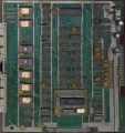
Image:1141_main_PCB_component_side.jpg|main PCB component side | |||
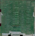
Image:1141_main_PCB_solder_side.jpg|main PCB solder side | |||
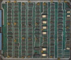
Image:1141_ROMs_PCB_component_side.jpg|ROMs PCB component side | |||
Image:1141_ROMs_PCB_solder_side.jpg|ROMs PCB solder side | |||
File:1141.zip|ROMs | |||
</gallery> | </gallery> | ||
| Line 71: | Line 114: | ||
[[Category:Any]] | [[Category:Any]] | ||
[[Category:Tafoid]] | [[Category:Tafoid]] | ||
[[Category:f205v]] | |||
[[Category:Dump complete]] | [[Category:Dump complete]] | ||
[[Category:Emulated]] | [[Category:Emulated]] | ||
Revision as of 20:34, 20 April 2017
| dumper | Any, f205v |
| date | 10/05/2013 |
| emulator | MAME 0.148u5 |
| dev | Tafoid |
| name | ccbootmr on ProgettoEMMA ccbootmr on Arcade Database |
| description | Crazy Climber (Model Racing bootleg) |
| year | 1980 |
| manufacturer | Model Racing |
Technical references
CPUs
| QTY | Type | clock | position | function |
|---|---|---|---|---|
| 1x | Z80CPUB1 | piggyback 6d | 8-bit Microprocessor - main | |
| 1x | AY-3-8910 | 6r main PCB | Programmable Sound Generator - sound | |
| 1x | MC3301P | 8p main PCB | Quad Operational Amplifier - sound | |
| 1x | oscillator | 18MHz | 0a ROMs PCB |
ROMs
| QTY | Type | position | status |
|---|---|---|---|
| 6x | TMS2716 | 6a,6c,6h,6k,6l,6n ROMs PCB | dumped |
| 7x | TMS2532 | 4c,4e,4f,4j,4k,4p,4r main PCB | dumped |
| 1x | TBP24S10N | piggyback 6d | dumped |
| 3x | PROM | 9c,9n,9p ROMs PCB | dumped |
RAMs
| QTY | Type | position |
|---|---|---|
| 2x | TMS2114L-20NL | 5a,5b main PCB |
| 2x | TMS2114L-20NL | 5h,5j ROMs PCB |
| 2x | TMS2114L-45NL | 1f,1h ROMs PCB |
| 6x | TMS2147H-7NL | 8j,8k,8l,8m,8n,8p ROMs PCB |
| 2x | Am9101 | 5a,5c ROMs PCB |
PLDs
| QTY | Type | position | status |
|---|---|---|---|
| 0x |
Others
1x 22x2 edge connector (main PCB)
1x 28x2 thin edge connector (main PCB)
2x 50 pins flat cable connector from main board to ROMs board
1x trimmer (volume)(main PCB)
1x 8 DIP switches bank (main PCB)
Notes
main PCB is marked: "MEF00274" and "17-33"
ROMs PCB is marked: "MEF00273" and "17-32"
update 20170420: a second PCB was found. Added pics, confirmed dump, correct labels.
Files
-
main PCB component side
-
main PCB solder side
-
ROMs PCB component side
-
ROMs PCB solder side
-
ROMs
1141


