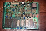
Cat and Mouse (type 02 program)
| dumper | f205v, Vernimark, Alessio, Corrado Tomaselli, Matteo |
| date | 13/05/2005 |
| emulator | MAME 0.100u3 |
| dev | Pierpaolo Prazzoli |
| name | catnmous on Arcade Database |
| description | Cat and Mouse (type 02 program) |
| year | 1982 |
| manufacturer | Zaccaria |
Technical references
CPUs
| QTY | Type | clock | position | function |
|---|---|---|---|---|
| 1x | 2650 | 9c main PCB | 8-bit Microprocessor - main | |
| 3x | 2636 | 2e,3e,5e main PCB | Programmable Video Interface | |
| 1x | 6802 | 1b sound PCB | 8-bit Microcontroller - sound | |
| 1x | 6821 | 1g sound PCB | Peripheral Interface Adapter | |
| 2x | AY-3-8910 | 1h,1i sound PCB | Programmable Sound Generator - sound | |
| 3x | LM3900 | 3i,2e,3b sound PCB | Quad Operational Amplifier - sound | |
| 1x | oscillator | ? | main PCB | |
| 1x | oscillator | ? | sound PCB |
ROMs
| QTY | Type | position | status |
|---|---|---|---|
| 9x | 2716 | from 02.1 to 02.9 main PCB | dumped |
| 3x | 2716 | 01.8g, 01.10g, 01.11g main PCB | dumped |
| 1x | 2732 | 02.10-11 main PCB | dumped |
| 1x | 2732 | 01.14l main PCB | dumped |
| 3x | 2732 | 1d,1e,1f sound PCB | dumped |
RAMs
| QTY | Type | position |
|---|---|---|
| 6x | uPD2114LC | 12f,13f,14f,15f,6e,7e |
PLDs
| QTY | Type | position | status |
|---|---|---|---|
| 1x | 82S100 | 10m main PCB | dumped |
Others
1x trimmer (volume)(sound PCB)
2x 8x2 switches DIP (main PCB)
Notes
This is the very same board you can find at "http://www.vernimark.com/arcade/archive/gameinfo.asp?GameID=99"
Dump is now complete, all previous dumps floating around on the net where partial.
update 20060118: We finally dumped the 82S100 and re-dumped one of the eprom (it's an 2732, not 2716)
update 20160207: Another EPROM was 2732 instead of 2716. Now the dump is really complete
update 20190826: Kold666 sent in a pinout for this board, here is what he says:
For the ones interested, I made a simple excel sheet to wire a Zaccaria Cat and Mouse to JAMMA.
There are a couple of interesting things:
- the PCB outputs negative colours much like Nintendo PCBs. So you need to invert them. It was totally unknown to me.
- on the manual green and blue are wrong. They need to be swapped to have the same colours as on the flyer (and MAME)
- inputs are matrix type but they are used in a way that you can wire all rows pins together and connect to GND.
update 20220213: thanks to Vernimark we now have the manual.
Files
-
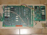
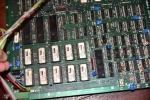
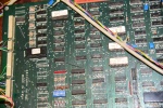
assembled PCBs component side
-
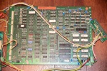
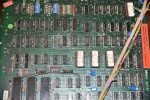
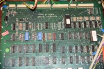
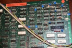
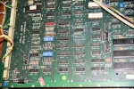
main PCB component side
-
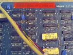
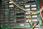
main PCB component side detail 1
-
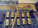
main PCB component side detail 2
-
main PCB component side detail 3
-
main PCB component side detail 4
-
main PCB component side detail 5
-
main PCB component side detail 6
-
main PCB component side detail 7
-
main PCB component side detail 8
-
main PCB component side detail 9
-
main PCB component side resistors detail
-
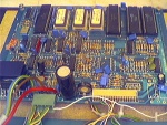
sound PCB component side 1
-
sound PCB component side 2
-
pinout
-
manual
174
