Cuore 1 (Italian, set 4): Difference between revisions
From Citylan
Jump to navigationJump to search
(Created page with "{| style="float: right;" border="1" cellpadding="3" cellspacing="0" |+ style="background:silver" | EMU Infos |- |dumper || f205v |- |date || 14/11/2020 |- |emulator || |- |de...") |
mNo edit summary |
||
| Line 32: | Line 32: | ||
!function | !function | ||
|- | |- | ||
|1x || [[6502|R65C02P2]] || 1.999MHz(@37) - 1.999MHz(@39) || u1 || 8-bit Microprocessor - main | |1x || [[6502|R65C02P2]] || 1.999MHz(@37) - 1.999MHz(@39) || 1st PCB u1 || 8-bit Microprocessor - main | ||
|- | |- | ||
|1x || [[6845|MC6845P]] || 1.999MHz(@21) - 15.99kHz(@39) - 62.47Hz(@40) || u8 || CRT Controller (CRTC) | |1x || [[6845|MC6845P]] || 1.999MHz(@21) - 15.99kHz(@39) - 62.47Hz(@40) || 1st PCB u8 || CRT Controller (CRTC) | ||
|- | |- | ||
|2x || [[6821|EF68B21P]] || - || u29,u30 || Peripheral Interface Adapter | |2x || [[6821|EF68B21P]] || - || 1st PCB u29,u30 || Peripheral Interface Adapter | ||
|- | |- | ||
|1x || [[AY-3-8910|89C10]] || 1.999MHz(@22) || u31 || Programmable Sound Generator - sound | |1x || [[AY-3-8910|89C10]] || 1.999MHz(@22) || 1st PCB u31 || Programmable Sound Generator - sound | ||
|- | |- | ||
| | | | ||
|- | |- | ||
|1x || oscillator || 16.000000MHz || os1 || | |1x || [[6502|R65C02P2]] || 1.999MHz(@37) - 1.999MHz(@39) || 2nd PCB u1 || 8-bit Microprocessor - main | ||
|- | |||
|1x || [[6845|HD46505P-2]] || 1.999MHz(@21) - 15.99kHz(@39) - 62.47Hz(@40) || 2nd PCB u8 || CRT Controller (CRTC) | |||
|- | |||
|2x || [[6821|EF6821P]] || - || 2nd PCB u29,u30 || Peripheral Interface Adapter | |||
|- | |||
|1x || [[AY-3-8910|YM2149F]] || 1.999MHz(@22) || 2nd PCB u31 || Programmable Sound Generator - sound | |||
|- | |||
| | |||
|- | |||
|1x || [[6502|R65C02P2]] || 1.998MHz(@37) - 1.998MHz(@39) || 3rd PCB u1 || 8-bit Microprocessor - main | |||
|- | |||
|1x || [[6845|HD46505P-2]] || 1.998MHz(@21) - 15.99kHz(@39) - 62.46Hz(@40) || 3rd PCB u8 || CRT Controller (CRTC) | |||
|- | |||
|2x || [[6821|EF6821P]] || - || 3rd PCB u29,u30 || Peripheral Interface Adapter | |||
|- | |||
|1x || [[AY-3-8910|KC89C72]] || 1.998MHz(@22) || 3rd PCB u31 || Programmable Sound Generator - sound | |||
|- | |||
| | |||
|- | |||
|1x || [[TDA2003|TDA2003]] || - || all PCBs u33 || Audio Amplifier - sound | |||
|- | |||
|1x || oscillator || 16.000000MHz || all PCBs os1 || | |||
|} | |} | ||
| Line 53: | Line 75: | ||
!status | !status | ||
|- | |- | ||
|1x || [[27256|TMS27C256]] || u2 || dumped | |1x || [[27256|TMS27C256]] || 1st PCB u2 || dumped | ||
|- | |- | ||
|2x || [[27256|HN27256G]] || u20,u21 || dumped | |2x || [[27256|HN27256G]] || 1st PCB u20,u21 || dumped | ||
|- | |- | ||
|1x || [[PROM|AM27S29PC]] || u25 || dumped | |1x || [[PROM|AM27S29PC]] || 1st PCB u25 || dumped | ||
|- | |||
| | |||
|- | |||
|3x || [[27256|27256]] || 2nd, 3rd PCB u2,u20,u21 || dumped | |||
|- | |||
|1x || [[PROM|N82S147AN]] || 2nd, 3rd PCB u25 || dumped | |||
|} | |} | ||
| Line 67: | Line 95: | ||
!position | !position | ||
|- | |- | ||
|1x || [[SRAM 8k x 8|KM6264BL-10]] || u13 | |1x || [[SRAM 8k x 8|KM6264BL-10]] || 1st PCB u13 | ||
|- | |||
|1x || [[SRAM 2k x 8|GM76C28A-10]] || 1st PCB u3 | |||
|- | |||
| | |||
|- | |- | ||
|1x || [[SRAM 2k x 8| | |1x || [[SRAM 8k x 8|HM6264LP-15]] || 2nd, 3rd PCB u13 | ||
|- | |||
|1x || [[SRAM 2k x 8|LC3517B-15]] || 2nd, 3rd PCB u3 | |||
|} | |} | ||
| Line 80: | Line 114: | ||
!status | !status | ||
|- | |- | ||
|2x || [[20v8|GAL20V8A-25LP]] || u22,u23 || read protected | |2x || [[20v8|GAL20V8A-25LP]] || 1st PCB u22,u23 || read protected | ||
|- | |||
|1x || [[16v8|PALCE16V8H-25PC/4]] || 1st PCB u5 || read protected | |||
|- | |||
| | |||
|- | |||
|2x || [[20v8|PALCE20V8-15PC]] || 2nd PCB u22,u23 || read protected | |||
|- | |||
|1x || [[16v8|GAL16V8AH-15LNC]] || 2nd PCB u5 || read protected | |||
|- | |||
| | |||
|- | |||
|2x || [[20v8|PALCE20V8H-25PC/4]] || 3rd PCB u22,u23 || read protected | |||
|- | |- | ||
|1x || [[16v8|PALCE16V8H-25PC/4]] || u5 || read protected | |1x || [[16v8|PALCE16V8H-25PC/4]] || 3rd PCB u5 || read protected | ||
|} | |} | ||
| Line 93: | Line 139: | ||
==Notes== | ==Notes== | ||
Not working<br> | Not working<br> | ||
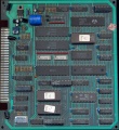
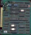
all PCBs are marked: "top" and "C.M.C. POOL 10" on component side<br> | |||
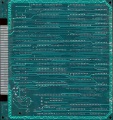
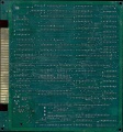
all PCBs are marked: "BOTTOM", "BF ENGINEERING" and "POOL 10 C.M.C" on solder side | |||
==Files== | ==Files== | ||
<gallery widths="150px"> | <gallery widths="150px"> | ||
Image:1719_PCB_component_side.jpg|PCB component side | Image:1719_PCB_component_side.jpg|1st PCB component side | ||
Image:1719_PCB_solder_side.jpg|PCB solder side | Image:1719_PCB_solder_side.jpg|1st PCB solder side | ||
Image:1719_disclaimer1.jpg|disclaimer 1 | Image:1719_2nd_PCB_component_side.jpg|2nd PCB component side | ||
Image:1719_disclaimer2.jpg|disclaimer 2 | Image:1719_2nd_PCB_solder_side.jpg|2nd PCB solder side | ||
Image:1719_error.jpg|error | Image:1719_rd_PCB_component_side.jpg|3rd PCB component side | ||
Image:1719_rd_PCB_solder_side.jpg|3rd PCB solder side | |||
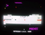
Image:1719_disclaimer1.jpg|PCB disclaimer 1 | |||
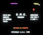
Image:1719_disclaimer2.jpg|PCB disclaimer 2 | |||
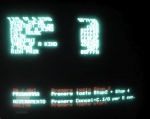
Image:1719_disclaimer3.jpg|disclaimer 3 | |||
Image:1719_error.jpg|1st PCB error | |||
Image:1719_error2.jpg|3rd PCB error | |||
Image:1719_how_to_play.jpg|how to play | |||
Image:1719_setup.jpg|setup | Image:1719_setup.jpg|setup | ||
File:1719.zip|ROMs | File:1719.zip|ROMs | ||
Revision as of 15:07, 30 November 2020
| dumper | f205v |
| date | 14/11/2020 |
| emulator | |
| dev |
| name | 1719 |
| description | Gambling Game on Pool 10 HW, set 2 |
| year | 1996 |
| manufacturer | C.M.C. |
Technical references
CPUs
| QTY | Type | clock | position | function |
|---|---|---|---|---|
| 1x | R65C02P2 | 1.999MHz(@37) - 1.999MHz(@39) | 1st PCB u1 | 8-bit Microprocessor - main |
| 1x | MC6845P | 1.999MHz(@21) - 15.99kHz(@39) - 62.47Hz(@40) | 1st PCB u8 | CRT Controller (CRTC) |
| 2x | EF68B21P | - | 1st PCB u29,u30 | Peripheral Interface Adapter |
| 1x | 89C10 | 1.999MHz(@22) | 1st PCB u31 | Programmable Sound Generator - sound |
| 1x | R65C02P2 | 1.999MHz(@37) - 1.999MHz(@39) | 2nd PCB u1 | 8-bit Microprocessor - main |
| 1x | HD46505P-2 | 1.999MHz(@21) - 15.99kHz(@39) - 62.47Hz(@40) | 2nd PCB u8 | CRT Controller (CRTC) |
| 2x | EF6821P | - | 2nd PCB u29,u30 | Peripheral Interface Adapter |
| 1x | YM2149F | 1.999MHz(@22) | 2nd PCB u31 | Programmable Sound Generator - sound |
| 1x | R65C02P2 | 1.998MHz(@37) - 1.998MHz(@39) | 3rd PCB u1 | 8-bit Microprocessor - main |
| 1x | HD46505P-2 | 1.998MHz(@21) - 15.99kHz(@39) - 62.46Hz(@40) | 3rd PCB u8 | CRT Controller (CRTC) |
| 2x | EF6821P | - | 3rd PCB u29,u30 | Peripheral Interface Adapter |
| 1x | KC89C72 | 1.998MHz(@22) | 3rd PCB u31 | Programmable Sound Generator - sound |
| 1x | TDA2003 | - | all PCBs u33 | Audio Amplifier - sound |
| 1x | oscillator | 16.000000MHz | all PCBs os1 |
ROMs
| QTY | Type | position | status |
|---|---|---|---|
| 1x | TMS27C256 | 1st PCB u2 | dumped |
| 2x | HN27256G | 1st PCB u20,u21 | dumped |
| 1x | AM27S29PC | 1st PCB u25 | dumped |
| 3x | 27256 | 2nd, 3rd PCB u2,u20,u21 | dumped |
| 1x | N82S147AN | 2nd, 3rd PCB u25 | dumped |
RAMs
| QTY | Type | position |
|---|---|---|
| 1x | KM6264BL-10 | 1st PCB u13 |
| 1x | GM76C28A-10 | 1st PCB u3 |
| 1x | HM6264LP-15 | 2nd, 3rd PCB u13 |
| 1x | LC3517B-15 | 2nd, 3rd PCB u3 |
PLDs
| QTY | Type | position | status |
|---|---|---|---|
| 2x | GAL20V8A-25LP | 1st PCB u22,u23 | read protected |
| 1x | PALCE16V8H-25PC/4 | 1st PCB u5 | read protected |
| 2x | PALCE20V8-15PC | 2nd PCB u22,u23 | read protected |
| 1x | GAL16V8AH-15LNC | 2nd PCB u5 | read protected |
| 2x | PALCE20V8H-25PC/4 | 3rd PCB u22,u23 | read protected |
| 1x | PALCE16V8H-25PC/4 | 3rd PCB u5 | read protected |
Others
1x 28x2 JAMMA edge connector
1x trimmer (volume)
1x 8 DIP switches bank (SW1)
1x battery 3.6V
Notes
Not working
all PCBs are marked: "top" and "C.M.C. POOL 10" on component side
all PCBs are marked: "BOTTOM", "BF ENGINEERING" and "POOL 10 C.M.C" on solder side
Files
-
1st PCB component side
-
1st PCB solder side
-
2nd PCB component side
-
2nd PCB solder side
-
3rd PCB component side
-
3rd PCB solder side
-
PCB disclaimer 1
-
PCB disclaimer 2
-
disclaimer 3
-
1st PCB error
-
3rd PCB error
-
how to play
-
setup
-
ROMs
1719
