Hot Bubble (Korea, with adult pictures): Difference between revisions
From Citylan
Jump to navigationJump to search
mNo edit summary |
mNo edit summary |
||
| Line 13: | Line 13: | ||
|+ style="background:silver" | PCB Infos | |+ style="background:silver" | PCB Infos | ||
|- | |- | ||
|name || ''' | |name || '''[http://adb.arcadeitalia.net/?mame=hotbubl hotbubl on Arcade Database]''' | ||
|- | |- | ||
|description || '''Hot Bubble (Korea, with adult pictures)''' | |description || '''Hot Bubble (Korea, with adult pictures)''' | ||
Latest revision as of 09:13, 7 June 2024
| dumper | Guru, f205v |
| date | 15/10/2004 |
| emulator | MAME 0.88u2 |
| dev | David Haywood |
| name | hotbubl on Arcade Database |
| description | Hot Bubble (Korea, with adult pictures) |
| year | 1998.07 |
| manufacturer | Afega (Pandora license) |
Technical references
CPUs
| QTY | Type | clock | position | function |
|---|---|---|---|---|
| 1x | MC68HC000P10 | 12MHz(@15) | main PCB u7 | 16/32-bit Microprocessor - main |
| 1x | unknown QFP208 | main PCB LTC1 | unknown | |
| 1x | unknown LCC64 | ROMs PCB LTC1 | unknown | |
| 1x | Z84C0006FEC | 4MHz(@7) | main PCB u127 | 8-bit Microprocessor - sound |
| 1x | AD-65 | 7.575MHz(@5) | main PCB u128 | 4-Channel Mixing ADCPM Voice Synthesis LSI - sound |
| 1x | BS901 | 4MHz(@23) | main PCB u124 | FM Operator Type-M (OPM) - sound |
| 1x | BS902 | main PCB u125 | D/A Converter (DAC) - sound | |
| 2x | IL324N | - | main PCB u130,u131 | Quad Operational Amplifier - sound |
| 1x | KA22065 | - | main PCB AMP22065 | Audio Power Amplifier - sound |
| 1x | oscillator | 12.000MHz | main PCB osc1 | |
| 1x | oscillator | 4.000MHz | main PCB osc |
ROMs
| QTY | Type | position | status |
|---|---|---|---|
| 1x | TMS27C512 | main PCB uc2,uc14 | dumped |
| 2x | AM27C010 | main PCB uc1,uc9 | dumped |
| 3x | AM27C020 | main PCB uc3,uc10,uc18 | dumped |
| 6x | FM27C040 | main PCB uc6,uc7,uc12,uc15,uc16,uc19 | dumped |
RAMs
| QTY | Type | position |
|---|---|---|
| 6x | HM61S16 | u32,u38,u51,u54,u75,u80 |
| 2x | GM76C88Al-15 | u56,u57 |
| 6x | GM76C256CLL-70 | u8,u14,u112,u116,u118,u120 |
PLDs
| QTY | Type | position | status |
|---|---|---|---|
| 0x |
Others
1x 28x2 JAMMA edge connector (main PCB)
3x 96 pins connectors from main PCB to ROMs PCB (CN1,CN2,CN3)
1x trimmer (volume) (main PCB)
2x 8 DIP switches banks (main PCB DIPSW1,DIPSW2)
Notes
main PCB is labelled: "3A 7/98" on component side
update 20210328: full redump, better description, better pics
Files
-
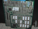
assembled PCBs 1
-
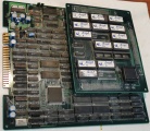
assembled PCBs 2
-
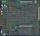
main PCB component side
-
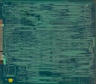
main PCB solder side
-
ROMs PCB component side
-
ROMs PCB solder side
-
Title
-
Intro
22


