Sub Hunter (Model Racing): Difference between revisions
mNo edit summary |
mNo edit summary |
||
| (5 intermediate revisions by the same user not shown) | |||
| Line 13: | Line 13: | ||
|+ style="background:silver" | PCB Infos | |+ style="background:silver" | PCB Infos | ||
|- | |- | ||
|name || ''' | |name || '''[http://adb.arcadeitalia.net/?mame=subhuntr subhuntr on Arcade Database]''' | ||
|- | |- | ||
|description || '''Sub Hunter (Model Racing)''' | |description || '''Sub Hunter (Model Racing)''' | ||
| Line 32: | Line 32: | ||
!function | !function | ||
|- | |- | ||
|1x || [[2621| | |1x || [[2621|CT430I]] || || main PCB B8 || Universal Sync Generator (PAL) - Video | ||
|- | |- | ||
| | |2x || [[2636|2636]] || || main PCB H5 L5 || Programmable Video Interface | ||
|- | |- | ||
|1x || [[2650|2650]] || OSC/2 = 1.7897725 MHz || main PCB F5 || 8-bit Microprocessor - main | |1x || [[2650|2650]] || OSC/2 = 1.7897725 MHz || main PCB F5 || 8-bit Microprocessor - main | ||
|- | |- | ||
|1x || oscillator || 3.579545 MHz || main PCB A9 || | |1x || oscillator || 3.579545 MHz || main PCB A9 || | ||
|- | |||
|1x || [[LM324|LM324]] || - || sound PCB A || Quad Operational Amplifier - sound | |||
|- | |||
|3x || [[LM741|LM741]] || - || sound PCB B,C,D || Operational Amplifier - sound | |||
|} | |} | ||
| Line 62: | Line 66: | ||
|- | |- | ||
|2x || [[SRAM 256 x 4|2101-1]] || main PCB B4,C4 | |2x || [[SRAM 256 x 4|2101-1]] || main PCB B4,C4 | ||
|} | |} | ||
| Line 80: | Line 82: | ||
1x 43x2 edge connector (main PCB)<br> | 1x 43x2 edge connector (main PCB)<br> | ||
1x 22x2 edge connector (sound PCB)<br> | 1x 22x2 edge connector (sound PCB)<br> | ||
6x trimmer (sound PCB VR1-VR6) | |||
==Notes== | ==Notes== | ||
| Line 96: | Line 98: | ||
RAM should be from 1C00 to 1FFF</pre> | RAM should be from 1C00 to 1FFF</pre> | ||
All components are dated "1979", it's a color game (as opposed to B/W Taito's "Depthcharge" or Gremlin's "Sub Hunter"), so we can assume release year to be 1979. | All components are dated "1979", it's a color game (as opposed to B/W Taito's "Depthcharge" or Gremlin's "Sub Hunter"), so we can assume release year to be 1979. | ||
----- | |||
update 20210426: from Cuavas and Tafoid: <s>the Model Racing Sub Hunter PCB has been stripped for parts, it's missing the main RAM (only text layer RAM present which the CPU can't read back), and one PVI.</s><br> | |||
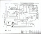
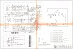
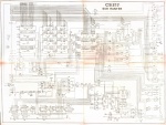
added schematics | |||
----- | |||
update 20210601: from Alessio: there is a fully working original cabinet in Alessio's arcade collection.<br>Confimed that there is a difference between schematics and real hardware.<br>On schematics there are:<br> | |||
2x [[2636|2636]] main PCB N5 - Programmable Video Interface<br> | |||
8x [[SRAM 256 x 4|2112-2]] main PCB G8,G9,H8,H9,L8,L9,M8,M9<br> | |||
which are not present on the real working PCB.<br> | |||
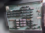
Added pics | |||
==Files== | ==Files== | ||
<gallery widths="150px"> | <gallery widths="150px"> | ||
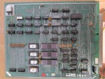
Image:1329_main_PCB_component_side.jpg|main PCB component side | Image:1329_main_PCB_component_side.jpg|1st main PCB component side | ||
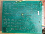
Image:1329_main_PCB_solder_side.jpg|main PCB solder side | Image:1329_main_PCB_solder_side.jpg|1st main PCB solder side | ||
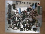
Image:1329_sub_PCB_component_side.jpg|sub PCB component side | Image:1329_sub_PCB_component_side.jpg|1st sub PCB component side | ||
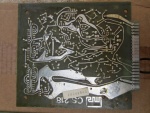
Image:1329_sub_PCB_solder_side.jpg|sub PCB solder side | Image:1329_sub_PCB_solder_side.jpg|1st sub PCB solder side | ||
Image:1329_schematics1.jpg|schematics 1 | |||
Image:1329_schematics2.jpg|schematics 2 | |||
Image:1329_schematics3.jpg|schematics 3 | |||
Image:1329_schematics4.jpg|schematics 4 | |||
Image:1329_2nd_main_PCB_component_side.jpg|2nd main PCB component side | |||
Image:1329_2nd_assembled_PCBs.jpg|2nd assembled PCBs | |||
Image:1329_cabinet.jpg|Cabinet | |||
</gallery> | </gallery> | ||
| Line 108: | Line 126: | ||
[[Category:Arcade]] | [[Category:Arcade]] | ||
[[Category:Piero Andreini]] | [[Category:Piero Andreini]] | ||
[[Category:Alessio]] | |||
[[Category:David Haywood]] | [[Category:David Haywood]] | ||
[[Category:Dump complete]] | [[Category:Dump complete]] | ||
Latest revision as of 14:46, 20 October 2024
| dumper | Piero Andreini |
| date | 18/10/2015 |
| emulator | MAME 0.167 |
| dev | David Haywood |
| name | subhuntr on Arcade Database |
| description | Sub Hunter (Model Racing) |
| year | 1979 |
| manufacturer | Model Racing |
Technical references
CPUs
| QTY | Type | clock | position | function |
|---|---|---|---|---|
| 1x | CT430I | main PCB B8 | Universal Sync Generator (PAL) - Video | |
| 2x | 2636 | main PCB H5 L5 | Programmable Video Interface | |
| 1x | 2650 | OSC/2 = 1.7897725 MHz | main PCB F5 | 8-bit Microprocessor - main |
| 1x | oscillator | 3.579545 MHz | main PCB A9 | |
| 1x | LM324 | - | sound PCB A | Quad Operational Amplifier - sound |
| 3x | LM741 | - | sound PCB B,C,D | Operational Amplifier - sound |
ROMs
| QTY | Type | position | status |
|---|---|---|---|
| 4x | 2708 | main PCB F7,H7,L7,N7 | dumped |
| 1x | N82S115 | main PCB B2 | dumped |
RAMs
| QTY | Type | position |
|---|---|---|
| 2x | 2101-1 | main PCB B4,C4 |
PLDs
| QTY | Type | position | status |
|---|---|---|---|
| 0x |
Others
1x 43x2 edge connector (main PCB)
1x 22x2 edge connector (sound PCB)
6x trimmer (sound PCB VR1-VR6)
Notes
main PCB is marked "CS217" and "20520/1L" and is labeled "09900278"
sub PCB is marked "CS218" and is labeled "10901903"
From Piero Andreini:
Memory map is:
Address		Name	Pos	Fluke CRC
0000-03FF	MR21	6F	3620
0400-07FF	MR22	6H	017D
0800-0BFF	MR25	6L	8464
0C00-0FFF	MR24	6N	FD3D

RAM should be from 1C00 to 1FFF
All components are dated "1979", it's a color game (as opposed to B/W Taito's "Depthcharge" or Gremlin's "Sub Hunter"), so we can assume release year to be 1979.
update 20210426: from Cuavas and Tafoid: the Model Racing Sub Hunter PCB has been stripped for parts, it's missing the main RAM (only text layer RAM present which the CPU can't read back), and one PVI.
added schematics
update 20210601: from Alessio: there is a fully working original cabinet in Alessio's arcade collection.
Confimed that there is a difference between schematics and real hardware.
On schematics there are:
2x 2636 main PCB N5 - Programmable Video Interface
8x 2112-2 main PCB G8,G9,H8,H9,L8,L9,M8,M9
which are not present on the real working PCB.
Added pics
Files
-
1st main PCB component side
-
1st main PCB solder side
-
1st sub PCB component side
-
1st sub PCB solder side
-
schematics 1
-
schematics 2
-
schematics 3
-
schematics 4
-
2nd main PCB component side
-
2nd assembled PCBs
-
Cabinet
1329
