Cuore 1 (Italian, set 5): Difference between revisions
(Created page with "{| style="float: right;" border="1" cellpadding="3" cellspacing="0" |+ style="background:silver" | EMU Infos |- |dumper || f205v |- |date || 14/11/2020 |- |emulator || |- |de...") |
mNo edit summary |
||
| (11 intermediate revisions by the same user not shown) | |||
| Line 6: | Line 6: | ||
|date || 14/11/2020 | |date || 14/11/2020 | ||
|- | |- | ||
|emulator || | |emulator || MAME 0.227 | ||
|- | |- | ||
|dev || | |dev || Osso | ||
|} | |} | ||
{| style="float: right;" border="1" cellpadding="3" cellspacing="0" | {| style="float: right;" border="1" cellpadding="3" cellspacing="0" | ||
|+ style="background:silver" | PCB Infos | |+ style="background:silver" | PCB Infos | ||
|- | |- | ||
|name || ''' | |name || '''[http://adb.arcadeitalia.net/?mame=cuoreunod cuoreunod on Arcade Database]''' | ||
|- | |- | ||
|description || ''' | |description || '''Cuore 1 (Italian, set 5)''' | ||
|- | |- | ||
|year || '''1996''' | |year || '''1996''' | ||
| Line 32: | Line 32: | ||
!function | !function | ||
|- | |- | ||
|1x || [[6502|R65C02P2]] || 1.999MHz(@37) - 1.999MHz(@39) || u1 || 8-bit Microprocessor - main | |1x || [[6502|R65C02P2]] || 1.999MHz(@37) - 1.999MHz(@39) || 1st,6th PCB u1 || 8-bit Microprocessor - main | ||
|- | |- | ||
| | |2x || [[6821|MC68B21CP]] || - || 1st,6th PCB u29,u30 || Peripheral Interface Adapter | ||
|- | |- | ||
| | |1x || [[AY-3-8910|89C10]] || 1.999MHz(@22) || 1st,6th PCB u31 || Programmable Sound Generator - sound | ||
|- | |- | ||
| | | | ||
|- | |- | ||
|1x || [[ | |1x || [[6502|G65SC02P-2]] || 1.999MHz(@37) - 1.999MHz(@39) || 2nd,3rd,4th,5th PCBs u1 || 8-bit Microprocessor - main | ||
|- | |- | ||
|1x || oscillator || 16.000000MHz || os1 || | |2x || [[6821|EF6821P]] || - || 2nd,3rd,4th,5th PCBs u29,u30 || Peripheral Interface Adapter | ||
|- | |||
|1x || [[AY-3-8910|KC89C72]] || 1.999MHz(@22) || 2nd,3rd,4th,5th PCBs u31 || Programmable Sound Generator - sound | |||
|- | |||
| | |||
|- | |||
|1x || [[6845|MC6845P]] || 1.999MHz(@21) - 15.99kHz(@39) - 62.47Hz(@40) || all PCBs u8 || CRT Controller (CRTC) | |||
|- | |||
|1x || [[TDA2003|TDA2003]] || - || all PCBs u33 || Audio Amplifier - sound | |||
|- | |||
|1x || oscillator || 16.000000MHz || all PCBs os1 || | |||
|} | |} | ||
| Line 53: | Line 63: | ||
!status | !status | ||
|- | |- | ||
| | |3x || [[27256|27256]] || all PCBs u2, u20, u21 || dumped | ||
|- | |||
| | |||
|- | |- | ||
|1x || [[ | |1x || [[PROM|AM27S29PC]] || 1st,6th PCB u25 || dumped | ||
|- | |- | ||
| | | | ||
|- | |- | ||
|1x || [[PROM| | |1x || [[PROM|N82S147AN]] || 2nd,3rd,4th,5th PCBs u25 || dumped | ||
|} | |} | ||
| Line 69: | Line 81: | ||
!position | !position | ||
|- | |- | ||
|1x || [[SRAM 8k x 8|KM6264BL-10]] || u13 | |1x || [[SRAM 8k x 8|KM6264BL-10]] || 1st,6th PCB u13 | ||
|- | |||
|1x || [[SRAM 2k x 8|GM76C28A-10]] || 1st,6th PCB u3 | |||
|- | |||
| | |||
|- | |||
|1x || [[SRAM 8k x 8|HM6264LP-15]] || 2nd,3rd,4th,5th PCBs u13 | |||
|- | |- | ||
|1x || [[SRAM 2k x 8| | |1x || [[SRAM 2k x 8|LC3517B-15]] || 2nd,3rd,4th,5th PCBs u3 | ||
|} | |} | ||
| Line 82: | Line 100: | ||
!status | !status | ||
|- | |- | ||
|2x || [[20v8|PALCE20V8H-25PC/4]] || u22,u23 || read protected | |2x || [[20v8|PALCE20V8H-25PC/4]] || 1st,2nd,3rd,4th,5th PCBs u22,u23 || read protected | ||
|- | |||
| | |||
|- | |||
|2x || [[20v8|GAL20V8A-25LP]] || 6th PCB u22,u23 || read protected | |||
|- | |||
| | |||
|- | |- | ||
|1x || [[16v8|PALCE16V8H-25PC/4]] || u5 || dumped | |1x || [[16v8|PALCE16V8H-25PC/4]] || all PCBs u5 || dumped | ||
|} | |} | ||
| Line 95: | Line 119: | ||
==Notes== | ==Notes== | ||
Not working<br> | Not working<br> | ||
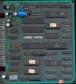
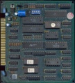
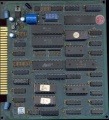
1st,6th PCBs are marked: "top" and "C.M.C. POOL 10" on component side<br> | |||
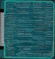
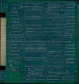
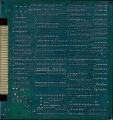
1st,6th PCBs are marked: "bottom", "BF ENGINEERING" and "POOL 10 C.M.C" on solder side<br> | |||
<br> | |||
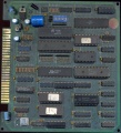
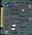
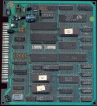
2nd,3rd,4th,5th PCBs are marked: "top" on component side<br> | |||
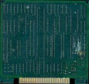
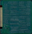
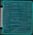
2nd,3rd,4th,5th PCBs are marked: "bottom" on solder side<br> | |||
2nd,3rd,4th,5th PCBs are labelled: "OK / 87.10.21 / 9" on component side | |||
----- | |||
update 20201206: found 5 other PCBs for the same game. Confirmed dump. | |||
==Files== | ==Files== | ||
<gallery widths="150px"> | <gallery widths="150px"> | ||
Image:1720_PCB_component_side.jpg|PCB component side | Image:1720_PCB_component_side.jpg|1st PCB component side | ||
Image:1720_PCB_solder_side.jpg|PCB solder side | Image:1720_PCB_solder_side.jpg|1st PCB solder side | ||
Image:1720_2nd_PCB_component_side.jpg|2nd PCB component side | |||
Image:1720_2nd_PCB_solder_side.jpg|2nd PCB solder side | |||
Image:1720_3rd_PCB_component_side.jpg|3rd PCB component side | |||
Image:1720_3rd_PCB_solder_side.jpg|3rd PCB solder side | |||
Image:1720_4th_PCB_component_side.jpg|4th PCB component side | |||
Image:1720_4th_PCB_solder_side.jpg|4th PCB solder side | |||
Image:1720_5th_PCB_component_side.jpg|5th PCB component side | |||
Image:1720_5th_PCB_solder_side.jpg|5th PCB solder side | |||
Image:1720_6th_PCB_component_side.jpg|6th PCB component side | |||
Image:1720_6th_PCB_solder_side.jpg|6th PCB solder side | |||
Image:1720_disclaimer.jpg|disclaimer | Image:1720_disclaimer.jpg|disclaimer | ||
Image:1720_error.jpg|error | Image:1720_error.jpg|error | ||
Image:1720_setup.jpg|setup | Image:1720_setup.jpg|setup | ||
</gallery> | </gallery> | ||
| Line 111: | Line 150: | ||
[[Category:Arcade]] | [[Category:Arcade]] | ||
[[Category:f205v]] | [[Category:f205v]] | ||
[[Category:Osso]] | |||
[[Category:Dump incomplete]] | [[Category:Dump incomplete]] | ||
[[Category: | [[Category:Emulated]] | ||
[[Category:MAME 0.227]] | |||
[[Category:1996]] | [[Category:1996]] | ||
[[Category:C.M.C.]] | [[Category:C.M.C.]] | ||
Latest revision as of 15:01, 27 September 2024
| dumper | f205v |
| date | 14/11/2020 |
| emulator | MAME 0.227 |
| dev | Osso |
| name | cuoreunod on Arcade Database |
| description | Cuore 1 (Italian, set 5) |
| year | 1996 |
| manufacturer | C.M.C. |
Technical references
CPUs
| QTY | Type | clock | position | function |
|---|---|---|---|---|
| 1x | R65C02P2 | 1.999MHz(@37) - 1.999MHz(@39) | 1st,6th PCB u1 | 8-bit Microprocessor - main |
| 2x | MC68B21CP | - | 1st,6th PCB u29,u30 | Peripheral Interface Adapter |
| 1x | 89C10 | 1.999MHz(@22) | 1st,6th PCB u31 | Programmable Sound Generator - sound |
| 1x | G65SC02P-2 | 1.999MHz(@37) - 1.999MHz(@39) | 2nd,3rd,4th,5th PCBs u1 | 8-bit Microprocessor - main |
| 2x | EF6821P | - | 2nd,3rd,4th,5th PCBs u29,u30 | Peripheral Interface Adapter |
| 1x | KC89C72 | 1.999MHz(@22) | 2nd,3rd,4th,5th PCBs u31 | Programmable Sound Generator - sound |
| 1x | MC6845P | 1.999MHz(@21) - 15.99kHz(@39) - 62.47Hz(@40) | all PCBs u8 | CRT Controller (CRTC) |
| 1x | TDA2003 | - | all PCBs u33 | Audio Amplifier - sound |
| 1x | oscillator | 16.000000MHz | all PCBs os1 |
ROMs
| QTY | Type | position | status |
|---|---|---|---|
| 3x | 27256 | all PCBs u2, u20, u21 | dumped |
| 1x | AM27S29PC | 1st,6th PCB u25 | dumped |
| 1x | N82S147AN | 2nd,3rd,4th,5th PCBs u25 | dumped |
RAMs
| QTY | Type | position |
|---|---|---|
| 1x | KM6264BL-10 | 1st,6th PCB u13 |
| 1x | GM76C28A-10 | 1st,6th PCB u3 |
| 1x | HM6264LP-15 | 2nd,3rd,4th,5th PCBs u13 |
| 1x | LC3517B-15 | 2nd,3rd,4th,5th PCBs u3 |
PLDs
| QTY | Type | position | status |
|---|---|---|---|
| 2x | PALCE20V8H-25PC/4 | 1st,2nd,3rd,4th,5th PCBs u22,u23 | read protected |
| 2x | GAL20V8A-25LP | 6th PCB u22,u23 | read protected |
| 1x | PALCE16V8H-25PC/4 | all PCBs u5 | dumped |
Others
1x 28x2 JAMMA edge connector
1x trimmer (volume)
1x 8 DIP switches bank (SW1)
1x battery 3.6V
Notes
Not working
1st,6th PCBs are marked: "top" and "C.M.C. POOL 10" on component side
1st,6th PCBs are marked: "bottom", "BF ENGINEERING" and "POOL 10 C.M.C" on solder side
2nd,3rd,4th,5th PCBs are marked: "top" on component side
2nd,3rd,4th,5th PCBs are marked: "bottom" on solder side
2nd,3rd,4th,5th PCBs are labelled: "OK / 87.10.21 / 9" on component side
update 20201206: found 5 other PCBs for the same game. Confirmed dump.
Files
-
1st PCB component side
-
1st PCB solder side
-
2nd PCB component side
-
2nd PCB solder side
-
3rd PCB component side
-
3rd PCB solder side
-
4th PCB component side
-
4th PCB solder side
-
5th PCB component side
-
5th PCB solder side
-
6th PCB component side
-
6th PCB solder side
-
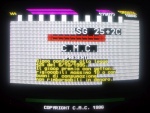
disclaimer
-
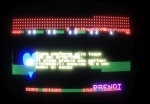
error
-
setup
1720
