Dog Fight (Thunderbolt): Difference between revisions
mNo edit summary |
mNo edit summary |
||
| (2 intermediate revisions by the same user not shown) | |||
| Line 13: | Line 13: | ||
|+ style="background:silver" | PCB Infos | |+ style="background:silver" | PCB Infos | ||
|- | |- | ||
|name || ''' | |name || '''[http://adb.arcadeitalia.net/?mame=dogfight dogfight on Arcade Database]''' | ||
|- | |- | ||
|description || '''Dog Fight (Thunderbolt)''' | |description || '''Dog Fight (Thunderbolt)''' | ||
|- | |- | ||
|year || '''1983''' | |year || '''1983.05.05''' | ||
|- | |- | ||
|manufacturer || '''Thunderbolt - Orca''' | |manufacturer || '''Thunderbolt - Orca''' | ||
| Line 32: | Line 32: | ||
!function | !function | ||
|- | |- | ||
|1x || [[Z80 | |1x || [[Z80]] || || sound PCB 3m || 8-bit Microprocessor - sound | ||
|- | |- | ||
|1x || [[ | |1x || [[AY-3-8910]] || || sound PCB 3j || Programmable Sound Generator - sound | ||
|- | |- | ||
|1x || [[ | |1x || [[uPC1181|C1182H]] || - || sound PCB 2a || Audio Amplifier - sound | ||
|- | |- | ||
|1x || oscillator || 18432 || | |1x || [[Z80|Z8400AB1]] || || main PCB 3c || 8-bit Microprocessor - main | ||
|- | |||
|1x || oscillator || 18432 || main PCB X1 || | |||
|} | |} | ||
| Line 49: | Line 51: | ||
!status | !status | ||
|- | |- | ||
|1x || [[2732|ET2732Q]] || | |1x || [[2732|ET2732Q]] || sound PCB 4n || sound - dumped | ||
|- | |- | ||
|2x || [[2732|ET2732Q]] || | |2x || [[2732|ET2732Q]] || main PCB 4m,4n || main - dumped | ||
|- | |- | ||
|2x || [[2764|HN482764G]] || | |2x || [[2764|HN482764G]] || main PCB 4f,4h || main - dumped | ||
|- | |- | ||
|3x || [[2732|ET2732Q]] || | |3x || [[2732|ET2732Q]] || ROMs PCB 3s,7n,7r || gfx - dumped | ||
|- | |- | ||
|2x || [[PROM|MMI6331-1]] || | |2x || [[PROM|MMI6331-1]] || ROMs PCB 2a,2b || dumped | ||
|} | |} | ||
| Line 67: | Line 69: | ||
!position | !position | ||
|- | |- | ||
|2x || [[SRAM 1k x 4|MM2114N]] || | |2x || [[SRAM 1k x 4|MM2114N]] || sound PCB 2p,2r | ||
|- | |||
|1x || [[SRAM 2k x 8|M58725P]] || main PCB 2k | |||
|- | |- | ||
| | |4x || [[SRAM 1k x 4|MM2114N]] || ROMs PCB 2r,2s,4n,4p | ||
|- | |- | ||
| | |2x || [[SRAM 1k x 4|uPD2114LC-2]] || ROMs PCB 2j,2l | ||
|- | |- | ||
|1x || [[SRAM 1k x 1|F93425PC]] || | |1x || [[SRAM 1k x 1|F93425PC]] || ROMs PCB 5c | ||
|- | |- | ||
|1x || [[SRAM 256 x 4|F93422PC]] || | |1x || [[SRAM 256 x 4|F93422PC]] || ROMs PCB 5d | ||
|} | |} | ||
| Line 89: | Line 93: | ||
===Others=== | ===Others=== | ||
1x 22x2 edge connector - | 1x 22x2 edge connector - sound PCB<br> | ||
1x 50 pins flat cable connector to | 1x 50 pins flat cable connector from sound PCB to main PCB and ROMs PCB<br> | ||
2x | 2x 8 DIP switches banks (sound PCB 3e, 4e)<br> | ||
1x trimmer (volume)<br> | 1x trimmer (volume) (sound PCB VR1)<br> | ||
1x 50 pins flat cable connector to | 1x 50 pins flat cable connector from main PCB to sound PCB and ROMs PCB<br> | ||
1x 50 pins flat cable connector to | 1x 50 pins flat cable connector from ROMs PCB to sound PCB and main PCB<br> | ||
=Notes= | =Notes= | ||
sound PCB is marked: "5-5-83" on solder side<br> | |||
My dump has gfx EPROM | main PCB is marked: "5-5-83" on component side<br> | ||
My dump has gfx EPROM 3S as 2732 (0x1000). The dump actually in MAME has df-6 as 2716 (0x0800), but both the readme for it and the markings on the PCB itself say it should be an 2732; therefore I think my dump is correct and the one actually in MAME should be amended. | |||
----- | |||
update 20220111: full redump, added pics, better description. | |||
=Files= | =Files= | ||
<gallery widths="150px"> | <gallery widths="150px"> | ||
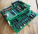
Image:810_assembled_PCBs.jpg|assembled PCBs | |||
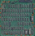
Image:810_sound_PCB_component_side.jpg|sound PCB component side | |||
Image:810_sound_PCB_solder_side.jpg|sound PCB solder side | |||
Image:810_main_PCB_component_side.jpg|main PCB component side | |||
Image:810_main_PCB_solder_side.jpg|main PCB solder side | |||
Image:810_ROMs_PCB_component_side.jpg|main PCB component side | |||
Image:810_ROMs_PCB_solder_side.jpg|main PCB solder side | |||
File:810.zip|ROMs | File:810.zip|ROMs | ||
</gallery> | </gallery> | ||
810 | |||
[[Category:Arcade]] | [[Category:Arcade]] | ||
[[Category:f205v]] | [[Category:f205v]] | ||
Latest revision as of 13:15, 10 October 2024
| dumper | f205v |
| dump date | 28/04/2009 |
| emulator | MAME 0.35b13 |
| dev | Zsolt Vasvari |
| name | dogfight on Arcade Database |
| description | Dog Fight (Thunderbolt) |
| year | 1983.05.05 |
| manufacturer | Thunderbolt - Orca |
Technical references
CPUs
| QTY | Type | clock | position | function |
|---|---|---|---|---|
| 1x | Z80 | sound PCB 3m | 8-bit Microprocessor - sound | |
| 1x | AY-3-8910 | sound PCB 3j | Programmable Sound Generator - sound | |
| 1x | C1182H | - | sound PCB 2a | Audio Amplifier - sound |
| 1x | Z8400AB1 | main PCB 3c | 8-bit Microprocessor - main | |
| 1x | oscillator | 18432 | main PCB X1 |
ROMs
| QTY | Type | position | status |
|---|---|---|---|
| 1x | ET2732Q | sound PCB 4n | sound - dumped |
| 2x | ET2732Q | main PCB 4m,4n | main - dumped |
| 2x | HN482764G | main PCB 4f,4h | main - dumped |
| 3x | ET2732Q | ROMs PCB 3s,7n,7r | gfx - dumped |
| 2x | MMI6331-1 | ROMs PCB 2a,2b | dumped |
RAMs
| QTY | Type | position |
|---|---|---|
| 2x | MM2114N | sound PCB 2p,2r |
| 1x | M58725P | main PCB 2k |
| 4x | MM2114N | ROMs PCB 2r,2s,4n,4p |
| 2x | uPD2114LC-2 | ROMs PCB 2j,2l |
| 1x | F93425PC | ROMs PCB 5c |
| 1x | F93422PC | ROMs PCB 5d |
PLDs
| QTY | Type | position | status |
|---|
Others
1x 22x2 edge connector - sound PCB
1x 50 pins flat cable connector from sound PCB to main PCB and ROMs PCB
2x 8 DIP switches banks (sound PCB 3e, 4e)
1x trimmer (volume) (sound PCB VR1)
1x 50 pins flat cable connector from main PCB to sound PCB and ROMs PCB
1x 50 pins flat cable connector from ROMs PCB to sound PCB and main PCB
Notes
sound PCB is marked: "5-5-83" on solder side
main PCB is marked: "5-5-83" on component side
My dump has gfx EPROM 3S as 2732 (0x1000). The dump actually in MAME has df-6 as 2716 (0x0800), but both the readme for it and the markings on the PCB itself say it should be an 2732; therefore I think my dump is correct and the one actually in MAME should be amended.
update 20220111: full redump, added pics, better description.
Files
-
assembled PCBs
-
sound PCB component side
-
sound PCB solder side
-
main PCB component side
-
main PCB solder side
-
main PCB component side
-
main PCB solder side
-
ROMs
810


