Crackshot (bootleg): Difference between revisions
From Citylan
Jump to navigationJump to search
mNo edit summary |
m (→RAMs) |
||
| (15 intermediate revisions by the same user not shown) | |||
| Line 1: | Line 1: | ||
{| | {| style="float: right;" border="1" cellpadding="3" cellspacing="0" | ||
|+ style="background:silver" | EMU Infos | |+ style="background:silver" | EMU Infos | ||
|- | |- | ||
| Line 10: | Line 10: | ||
|dev || | |dev || | ||
|} | |} | ||
{| | {| style="float: right;" border="1" cellpadding="3" cellspacing="0" | ||
|+ style="background:silver" | PCB Infos | |+ style="background:silver" | PCB Infos | ||
|- | |- | ||
|name || ''' | |name || '''817''' | ||
|- | |- | ||
|description || '''Crackshot (bootleg)''' | |description || '''Crackshot (bootleg)''' | ||
| Line 28: | Line 28: | ||
!QTY | !QTY | ||
!Type | !Type | ||
!clock | |||
!position | !position | ||
!function | !function | ||
|- | |- | ||
|1x || [[6809|MC6809P]] || sound PCB || sound | |1x || [[6809|MC6809P]] || || sound PCB || 8-bit Microprocessor - sound | ||
|- | |- | ||
|1x || [[6844|MC6844P]] || sound PCB || | |1x || [[6844|MC6844P]] || || sound PCB || Direct Memory Access Controller (DMAC) | ||
|- | |- | ||
|1x || [[TDA2002]] || sound PCB || sound | |1x || [[TDA2002]] || || sound PCB || Audio Amplifier - sound | ||
|- | |- | ||
|1x || [[6809|S68B09EP]] || main PCB || main | |1x || [[6809|S68B09EP]] || || main PCB || 8-bit Microprocessor - main | ||
|- | |- | ||
|1x || [[YM2413|UM3567 | |1x || [[YM2413|UM3567]] || || u45 || FM Operator Type-LL - sound | ||
|- | |||
|1x || oscillator || 13.000 || main PCB || | |||
|} | |} | ||
===ROMs=== | ===ROMs=== | ||
| Line 74: | Line 75: | ||
!position | !position | ||
|- | |- | ||
|2x || [[1k x 4|NMC2148HJ]] || sound PCB | |2x || [[SRAM 1k x 4|NMC2148HJ]] || sound PCB | ||
|- | |- | ||
|1x || [[2k x 8|HM6116LP]] || sound PCB | |1x || [[SRAM 2k x 8|HM6116LP]] || sound PCB | ||
|- | |- | ||
|8x || [[1k x 4|NMC2148HJ]] || main PCB | |8x || [[SRAM 1k x 4|NMC2148HJ]] || main PCB | ||
|- | |- | ||
|4x || [[8k x 8|TC5565]] || main PCB | |4x || [[SRAM 8k x 8|TC5565]] || main PCB | ||
|- | |- | ||
|6x || [[2k x 8|TMM2015BP]] || main PCB | |6x || [[SRAM 2k x 8|TMM2015BP]] || main PCB | ||
|- | |- | ||
|2x || [[2k x 8|MCM2018AN]] || main PCB | |2x || [[SRAM 2k x 8|MCM2018AN]] || main PCB | ||
|} | |} | ||
| Line 110: | Line 111: | ||
1x 4x2 switches dip (main PCB)<br> | 1x 4x2 switches dip (main PCB)<br> | ||
=Notes= | |||
Not working | Not working<br> | ||
This is a bootleg PCB, with EPROM content arranged in a different way compared to the original, and one single PROM of difference | This is a bootleg PCB, with EPROM content arranged in a different way compared to the original, and one single PROM of difference | ||
| Line 124: | Line 124: | ||
</gallery> | </gallery> | ||
817 | |||
[[Category:Arcade]] | [[Category:Arcade]] | ||
[[Category:f205v]] | [[Category:f205v]] | ||
Latest revision as of 21:06, 21 September 2014
| dumper | f205v |
| dump date | 15/05/2009 |
| emulator | |
| dev |
| name | 817 |
| description | Crackshot (bootleg) |
| year | 1985 |
| manufacturer |
Technical references
CPUs
| QTY | Type | clock | position | function |
|---|---|---|---|---|
| 1x | MC6809P | sound PCB | 8-bit Microprocessor - sound | |
| 1x | MC6844P | sound PCB | Direct Memory Access Controller (DMAC) | |
| 1x | TDA2002 | sound PCB | Audio Amplifier - sound | |
| 1x | S68B09EP | main PCB | 8-bit Microprocessor - main | |
| 1x | UM3567 | u45 | FM Operator Type-LL - sound | |
| 1x | oscillator | 13.000 | main PCB |
ROMs
| QTY | Type | position | status |
|---|---|---|---|
| 4x | TMS27C256 | sound PCB 11,12,13,14 | dumped |
| 1x | TMS2764 | sound PCB 1H | dumped |
| 4x | TMS27C256 | main PCB 3,4,6,8 | dumped |
| 1x | TMM27256 | main PCB 2 | dumped |
| 1x | AM27256 | main PCB 5 | dumped |
| 1x | 6331-1 | main PCB 3 | dumped |
| 8x | 63S141N | main PCB 2,4,5,6,7,8,9,12 | dumped |
RAMs
| QTY | Type | position |
|---|---|---|
| 2x | NMC2148HJ | sound PCB |
| 1x | HM6116LP | sound PCB |
| 8x | NMC2148HJ | main PCB |
| 4x | TC5565 | main PCB |
| 6x | TMM2015BP | main PCB |
| 2x | MCM2018AN | main PCB |
PLDs
| QTY | Type | position | status |
|---|
Others
1x 22x2 edge connector (sound PCB)
1x 50 pins flat cable connector to main (sound PCB)
1x 26 pins flat cable connector to main (sound PCB)
1x 12 legs connector (sound PCB)
1x 5 legs connector (sound PCB)
1x trimmer (volume) (sound PCB)
1x 8x2 switches dip (sound PCB)
1x 50 pins flat cable connector to sound (main PCB)
1x 26 pins flat cable connector to sound (main PCB)
1x 5 legs connector (main PCB)
1x 4x2 switches dip (main PCB)
Notes
Not working
This is a bootleg PCB, with EPROM content arranged in a different way compared to the original, and one single PROM of difference
Files
-
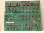
main PCB component side
-
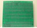
main PCB solder side
-
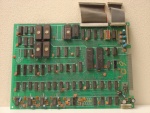
sound PCB component side
-
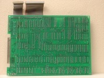
sound PCB solder side
-
ROMs
817


