Indianapolis (bootleg of Turbo): Difference between revisions
From Citylan
Jump to navigationJump to search
(Created page with "{| style="float: right;" border="1" cellpadding="3" cellspacing="0" |+ style="background:silver" | EMU Infos |- |dumper || f205v |- |date || 31/07/2006 |- |emulator || MAME 0....") |
mNo edit summary |
||
| Line 13: | Line 13: | ||
|+ style="background:silver" | PCB Infos | |+ style="background:silver" | PCB Infos | ||
|- | |- | ||
|name || ''' | |name || '''[http://adb.arcadeitalia.net/?mame=turbobl turbobl on Arcade Database]''' | ||
|- | |- | ||
|description || '''Indianapolis (bootleg of Turbo)''' | |description || '''Indianapolis (bootleg of Turbo)''' | ||
Latest revision as of 20:03, 6 October 2024
| dumper | f205v |
| date | 31/07/2006 |
| emulator | MAME 0.164 |
| dev | David Haywood |
| name | turbobl on Arcade Database |
| description | Indianapolis (bootleg of Turbo) |
| year | 1981 |
| manufacturer |
Technical references
CPUs
| QTY | Type | clock | position | function |
|---|---|---|---|---|
| 1x | NEC D780C | main PCB | 8-bit Microprocessor - main | |
| 1x | P8279 | main PCB | Programmable Keyboard / Display Interface | |
| 4x | P8255 | main PCB | Programmable Peripheral Interface | |
| 1x | DAC0800LCN | ROMs PCB | 8-Bit Digital-to-Analog Converter - sound | |
| 1x | LF351N | ROMs PCB | Wide bandwidth single JFET operational amplifier - sound | |
| 1x | oscillator | 19.998 | main PCB |
ROMs
| QTY | Type | position | status |
|---|---|---|---|
| 7x | TMS2516 | main PCB | dumped |
| 3x | D2764 | main PCB | dumped |
| 1x | TBP24S10 | main PCB | dumped |
| 1x | TBP28L22N | main PCB | dumped |
| 13x | D2763 | ROMs PCB | dumped |
| 4x | 74S288 | ROMs PCB | dumped |
| 2x | TBP24S41 | ROMs PCB | dumped |
RAMs
| QTY | Type | position |
|---|
PLDs
| QTY | Type | position | status |
|---|---|---|---|
| 0x |
Others
1x 50 pins flat cable connector (main PCB CN8)
1x 26 pins flat cable connector (main PCB CN7)
1x 6 legs connector (main PCB CN6)
1x 18 legs connector (main PCB CN5)
1x 6 legs connector (main PCB CN4)
1x 12 legs connector (main PCB CN3)
1x 6 legs connector (ROMs PCB)
2x 50 pins flat cable connector from main board to ROMs board (CN1 & CN2)
2x trimmers (ROMs PCB)
2x 8 DIP switches banks (main PCB)
2x red LEDs (main PCB)
1x red LEDs (ROMs PCB)
Notes
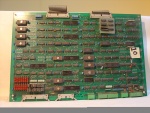
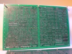
main PCB is marked: "CPU BOARD"
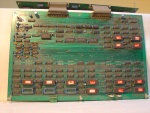
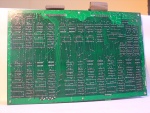
ROMs PCB is marked: "ROM BOARD"
Files
-
main PCB component side
-
main PCB solder side
-
ROMs PCB component side
-
ROMs PCB solder side
446


