Royal Card (Austrian, set 2): Difference between revisions
From Citylan
Jump to navigationJump to search
mNo edit summary |
m (WikiSysop moved page Royal Card (austrian, set 2) to Royal Card (Austrian, set 2) without leaving a redirect) |
||
| (5 intermediate revisions by the same user not shown) | |||
| Line 6: | Line 6: | ||
|date || 02/09/2005 | |date || 02/09/2005 | ||
|- | |- | ||
|emulator || MAME 0. | |emulator || MAME 0.99u8 | ||
|- | |- | ||
|dev || Roberto Fresca | |dev || Roberto Fresca | ||
| Line 39: | Line 39: | ||
|- | |- | ||
|1x || [[AY-3-8910|KC89C72]] || || || Programmable Sound Generator - sound | |1x || [[AY-3-8910|KC89C72]] || || || Programmable Sound Generator - sound | ||
|- | |||
|1x || [[TDA2003|TDA2003]] || || || Audio Amplifier - sound | |||
|- | |- | ||
|1x || oscillator || 16.000MHz || || | |1x || oscillator || 16.000MHz || || | ||
| Line 82: | Line 84: | ||
1x 28x2 edge connector<br> | 1x 28x2 edge connector<br> | ||
1x 10x2 edge connector<br> | 1x 10x2 edge connector<br> | ||
1x 3 legs connector (solder side)<br> | 1x 3 legs connector (solder side, connected to trimmer)<br> | ||
1x trimmer (volume)<br> | 1x trimmer (volume)<br> | ||
1x 8x2 switches DIP<br> | 1x 8x2 switches DIP<br> | ||
| Line 88: | Line 90: | ||
==Notes== | ==Notes== | ||
PCB is marked: "LC 0-917 BIS" on component side<br> | |||
PCB is marked: "LS 0-917 BIS" on solder side<br> | |||
PCB is labeled: "7/97" on sodler side | |||
==Files== | ==Files== | ||
Latest revision as of 13:49, 12 March 2024
| dumper | f205v |
| date | 02/09/2005 |
| emulator | MAME 0.99u8 |
| dev | Roberto Fresca |
| name | royalcrda on ProgettoEMMA royalcrda on Arcade Database |
| description | Royal Card (Austrian, set 2) |
| year | 1991 |
| manufacturer | TAB Austria |
Technical references
CPUs
| QTY | Type | clock | position | function |
|---|---|---|---|---|
| 1x | R65C02P2 | 8-bit Microprocessor - main | ||
| 1x | HD6845SP | CRT Controller (CRTC) | ||
| 2x | EF6821P | Peripheral Interface Adapter PIA | ||
| 1x | KC89C72 | Programmable Sound Generator - sound | ||
| 1x | TDA2003 | Audio Amplifier - sound | ||
| 1x | oscillator | 16.000MHz |
ROMs
| QTY | Type | position | status |
|---|---|---|---|
| 3x | TMS27C512 | dumped | |
| 1x | AM27S29APC | dumped |
RAMs
| QTY | Type | position |
|---|---|---|
| 1x | KM62256ALP-10 | |
| 1x | HM6116-3L |
PLDs
| QTY | Type | position | status |
|---|---|---|---|
| 1x | PALCE16V8H-25 | read protected |
Others
1x 28x2 edge connector
1x 10x2 edge connector
1x 3 legs connector (solder side, connected to trimmer)
1x trimmer (volume)
1x 8x2 switches DIP
1x battery 3.6V
Notes
PCB is marked: "LC 0-917 BIS" on component side
PCB is marked: "LS 0-917 BIS" on solder side
PCB is labeled: "7/97" on sodler side
Files
-
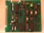
PCB component side
-
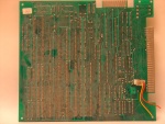
PCB solder side
-
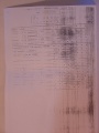
Dip switches
-
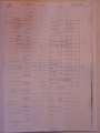
Connector


225